Matching active stereo camera specs to part size and surface in 3D scanning
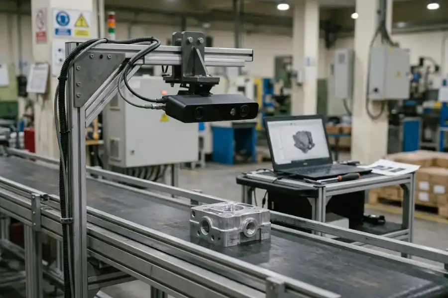
Integrators scoping a 3D scanning or measurement cell usually narrow the field to three technologies. These are active stereo, structured light and laser triangulation. An active stereo 3D camera for machine vision integration captures a full depth frame in a single exposure, which changes how it handles moving parts, cycle time and cabling. Structured light and laser triangulation trade some of that speed for finer detail on static or conveyed parts. The right choice depends less on the technology label than on five variables. These are working distance, depth noise at that distance, surface behavior, motion and how the data lands in your inspection software.
Three ways to build a point cloud
Active stereo uses two IR cameras a fixed baseline apart, plus a projector that adds texture to the scene. The camera finds the same feature in both images and converts the disparity into depth. Because the projected pattern only adds texture, ambient texture on the part contributes to matching as well.
Structured light projects a known pattern and reads depth from how the pattern deforms. Single-shot systems capture one coded pattern per frame. Multi-shot phase-shift systems project a sequence of fringes and combine them, which yields fine detail but needs the part to hold still for the whole sequence.
Laser triangulation projects a line and images it from an offset angle. Each frame gives one high-resolution profile. A full 3D surface comes from moving the part or the sensor, usually against an encoder.
Working distance sets everything else
Start with the standoff the cell allows. Conveyor clearance, robot reach and bin depth usually fix it before any camera enters the discussion. Then check two numbers on the datasheet. The first is the minimum distance, below which the camera returns no depth. The second is the optimal or ideal range, where the vendor’s noise figures apply.
A camera rated to 10 m is not automatically a good scanner at 0.3 m. Field of view matters here too. A wide lens covers a whole tote at short range, but each pixel then spans more of the part, which limits the smallest feature you can resolve.
Depth noise at your working distance
For a stereo pair, depth error grows with the square of distance and falls as baseline and focal length increase. Doubling the standoff roughly quadruples the noise. That is why a percentage figure quoted at 2 m says little about performance at 0.5 m or 4 m.
Read the test conditions behind any noise figure. Most vendors measure RMS deviation from a fitted plane on a bright, flat target over a central region of the image. That describes precision on an ideal surface. It does not describe absolute accuracy on a dark casting with edges and holes. For metrology, plan to verify against a gauge block or reference part at the real standoff and on the real material.
It also pays to look at the cloud itself before trusting any statistic. Importing a captured PLY file into Blender and using the Blender keyboard shortcuts to orbit, pan and zoom makes holes, flying pixels and warped edges far quicker to spot than a table of numbers.
Shiny, dark and transparent surfaces
Specular parts cause trouble for every optical method. Machined aluminum, polished steel and glossy plastics reflect the projected light away from the sensor or back as a saturated hotspot. In a stereo pair, the two cameras see highlights in different places, so matching fails and the point cloud shows holes. Tilting the camera off the surface normal often helps more than any setting change.
Dark parts are the opposite problem. Some black plastics and rubbers absorb strongly in the near infrared, so little projected light returns. Check the minimum target reflectivity the vendor specifies, then test your darkest part at your longest standoff.
Transparent and translucent parts defeat all three technologies in their standard form. Light passes through or scatters inside the material, and the measured surface ends up somewhere behind the real one.
Projector pattern and motion tolerance
Motion decides more selections than integrators expect. Active stereo forms depth from one exposure per frame. With global shutter IR sensors, a moving part is captured at one instant, so the remaining limit is exposure time and the resulting blur.
Multi-shot structured light needs a static part across the full pattern sequence. Any vibration or conveyor movement during that window corrupts the result. Laser triangulation needs motion to build a surface at all, so it pairs naturally with a conveyor but needs an encoder and a stable transport speed.
When several cameras scan one part from different angles, their projectors can interfere. Hardware synchronization lets you time exposures so each camera sees its own pattern, and it keeps frames from different views aligned in time.
If frames start dropping once several cameras stream together, the host PC is a common culprit. The Task Manager keyboard shortcut (Ctrl+Shift+Esc on Windows) opens it instantly, so you can see whether CPU or memory is saturated without leaving your capture software for long.
Feeding a metrology or inspection pipeline
The camera is one stage in a chain. Check that it outputs depth maps and point clouds in a format your software reads directly, and that depth-to-color alignment happens in the camera rather than on the host. Confirm SDK wrappers exist for the language your team uses. Open-source libraries such as Open3D and PCL handle plane fitting, segmentation and volume calculation once the cloud arrives.
A lot of this SDK work happens in an Ubuntu terminal, where a few Linux command line shortcuts, such as reverse history search, save real time when you are restarting capture scripts all day.
For repeatable measurement, plan for temperature. Optical cores drift as they warm, so a camera that reports its internal temperatures lets you log drift and compensate for it. For static parts, averaging several frames reduces random noise at the cost of cycle time.
The Gemini 2 as a worked example
Orbbec’s Gemini 2 sits under the stereo vision camera category on orbbec.com, and its spec table lists the depth technology as active stereo IR. The figures below come from the live product page and the Gemini 2 Datasheet v1.0 published on orbbec.com.
Depth modes and range
The camera has a 50 mm baseline and an 850 nm wavelength. The IR sensors use a global shutter and the color sensor uses a rolling shutter. Depth processing runs inside the camera on Orbbec’s MX6600 ASIC, so the host receives finished depth rather than raw image pairs. The depth field of view is H91° × V66°.
The datasheet lists three depth modes. Unbinned Dense Default runs at up to 1280 × 800 and 30 fps, with a range of 0.15 to 10 m and an optimal range of 0.20 to 5.0 m. Unbinned Sparse Default covers the same resolutions and range while balancing accuracy against power. Binned Sparse Default runs at 640 × 400 at up to 60 fps, with an optimal range of 0.15 to 2.5 m and a smaller blind zone. For bin inspection at short standoff, the binned mode is worth testing because of its frame rate and near-range behavior.
Noise and accuracy figures
Orbbec specifies depth accuracy of ≤2% at 2 m, measured at 1280 × 800. The test target is a flat plane with reflectivity above 80%, evaluated over the central 81% of the depth map. The figure is the RMS distance of valid points from a best-fit plane. At 2 m, 2% works out to 40 mm. That rules out fine dimensional work at that distance, but because stereo noise scales with the square of distance, the same camera at 0.5 m sits in a different class. The datasheet also states that the camera measures objects with reflectivity above 10% out to 10 m, and that actual accuracy varies with distance and object.
Integration details
A single USB 3.0 Type-C cable carries power and data. The product page lists average power under 2.5 W. An 8-pin connector supports multi-camera synchronization, and the datasheet gives a frame time difference of ≤3 ms between devices with auto exposure off. Laser, IR sensor and IMU temperatures can be read through API commands, which supports the drift logging described earlier. Dump those readings to a CSV and a handful of Microsoft Excel shortcuts will get you a drift-versus-time chart in a couple of minutes.
The camera measures 90 × 25 × 30 mm and weighs 98 g, with one 1/4-20 UNC mount and two M3 mounts. It is rated for 0 to 40°C in indoor and semi-outdoor settings. For integrators building an enclosure, the datasheet specifies a protective window transmittance of at least 92% across the IR band at 858 ± 20 nm. The open-source Orbbec SDK v2 runs on Windows, Ubuntu, macOS and Android, with ROS and ROS 2 wrappers and Python support.
In practice, the Gemini 2 fits bin inspection, fill-level checks, part presence and coarse dimensioning across its optimal range. For small parts at very short standoff, Orbbec’s Gemini 305 is the closer-range option, with a 4 cm minimum working distance and an ideal range of 7 to 50 cm.
What each technology cannot do
Active stereo cannot match the micron-scale detail of a laser line profiler on a conveyed part. Its noise also climbs quickly with distance, so a long standoff costs precision. It struggles on low-texture specular surfaces where the two views disagree.
Structured light in its multi-shot form cannot scan moving parts. Single-shot versions trade resolution for speed. Both depend on the projected pattern returning cleanly, so shiny and very dark parts cause gaps.
Laser triangulation cannot capture a full area in one shot. It needs controlled motion, and it shows occlusion shadows behind tall features because the laser and camera view the part from different angles.
None of the three handles transparent material without coatings or a different sensing method.
Matching the camera to the part
Write down the smallest feature you need to measure, the standoff the cell allows and whether the part moves during capture. Then take the vendor’s noise figure, scale it to your distance and compare it against your tolerance. If the margin is thin, test on your darkest and shiniest production parts before committing. Doing this before you request quotes saves days of back and forth with vendors. The datasheet sets expectations. The test on real parts settles the choice.